Choose one
or multiple languages
0,1,1
- German
- English
- Chinese
- Spanish
Notch effect
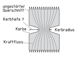
A notch effect occurs, for example, at notches (Design-related changes in cross-section) in a component and weakens the component. Metallurgical notches are also subject to notch effect forces. Welded joints are one example.
The stress is concentrated in the notch's cross-section, because the cross-sectional area is smaller here than where the cross-section is intact. The relevant parameter is the stress concentration factor ${{\alpha }_{c}}$.
The notch sensitivity n, another important parameter, is a measure of the supporting effect of a Force acting against the stress concentrations.
The fatigue notch factor ${{\beta }_{n}}$ is calculated from the notch sensitivity n and the stress concentration factor ${{\alpha }_{c}}$ as follows: ${{\beta }_{c}}=\frac{{{\alpha }_{c}}}{n}$
In practice, some components are deliberately given notches to distribute the stress flow in the component and achieve a homogeneous flow of force. The larger the notch radius, the more uniform the flow of force. By concentrating the lines of force around it, the notch increases the stress. This increase depends on the notch's shape and size.
In some cases, pre-determined breaking points are incorporated for safety reasons. They are defined by notches on components.
Kerbwirkung
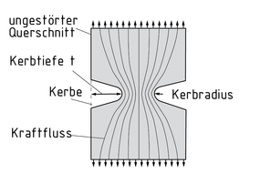
Eine Kerbwirkung tritt z. B. an Kerben (konstruktionsbedingten Querschnittsänderungen) eines Bauteiles auf und schwächt dieses. Auch an metallurgischen Kerben wie etwa an Schweißverbindungen entstehen Kerbwirkungskräfte.
Im Querschnitt der Kerbe konzentriert sich die Spannung, weil dort die Querschnittsfläche kleiner als im ungestörten Querschnitt ausfällt. Die Kenngröße hierfür ist die Formzahl ${{\alpha }_{k}}$.
Die Stützziffer n, eine weitere wichtige Größe, ist ein Maß für die Stützwirkung, eine entgegen der Spannungsspitzen wirkende Kraft.
Aus der Stützziffer n und der Formzahl ${{\alpha }_{k}}$ ergibt sich die Kerbwirkungszahl ${{\beta }_{k}}$ wie folgt: ${{\beta }_{k}}=\frac{{{\alpha }_{k}}}{n}$
In der Praxis werden Bauteile zum Teil bewusst mit Kerben versehen, um den Spannungsfluss im Bauteil zu verteilen und einen homogenen Kraftfluss zu erzielen. Je größer der Kerbradius ist, desto gleichmäßiger kann der Kraftfluss erfolgen. Die Kerbe führt durch das Zusammendrängen der Kraftlinien im Bereich der Kerbe zu einer Spannungserhöhung. Die Spannungserhöhung ist abhängig von Form und Größe der Kerbe.
Aufgrund von Sicherheitsaspekten werden zum Teil Sollbruchstellen eingeführt. Sie sind durch Kerben an Bauteilen definiert.
缺口效应
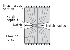
缺口效应通常发生在构件的缺口(横截面的设计变化)局部区域,降低构件的整体性能。冶金缺口也受到缺口效应的影响,例如焊接接头。
由于缺口处横截面最小所以应力集中在缺口的横截面。有关参数为应力集中系数 ${{\alpha }_{c}}$ 。
缺口敏感性 n,是另一个重要参数,是衡量抵抗应力集中的支撑效果的量度。
疲劳缺口系数 ${{\beta }_{n}}$ 可以由缺口敏感性 n 和应力集中系数 ${{\alpha }_{c}}$ 来计算,公式如下: ${{\beta }_{c}}=\frac{{{\alpha }_{c}}}{n}$
实际上,有时特意在构件上设计缺口来分配压力流,以达到均匀的压力流。一般缺口半径越大,力越均匀。通过把力集中在它周围,缺口集中了应力。应力增量取决于缺口的形状和大小。
在某些情况下,预先在构件上确定强度极限点是出于安全原因。这种强度极限点就表现为构件的缺口。
缺口处的应力剖面
Efecto de entalladura
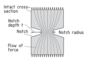
Un efecto de entalladura ocurre, por ejemplo, en muescas (cambios relacionados con el diseño de la sección) en un componente y debilitan el componente. Las muescas metalúrgicas también se someten a fuerzas de efecto de entalladura. Las uniones de soldadura son un ejemplo.
El esfuerzo se concentra en la sección de la muesca, porque el área de sección es menor aquí que donde la sección está intacta. El parámetro relevante es el factor de concentración de esfuerzo ${{\alpha }_{c}}$ .
La sensibilidad de muesca n, otro parámetro importante, es una medida del efecto de soporte de una fuerza que actúa contra las concentraciones de esfuerzo.
El factor de muesca de fatiga ${{\beta }_{n}}$ se calcula a partir de la sensibilidad de la muesca n y el factor de concentración de esfuerzos ${{\alpha }_{c}}$ , del siguiente modo: ${{\beta }_{c}}=\frac{{{\alpha }_{c}}}{n}$
En la práctica, a algunos componentes se les hacen deliberadamente muescas para distribuir el flujo de los esfuerzos en el componente y lograr un flujo homogéneo de las fuerzas. Mientras más grande sea el radio de la muesca, más uniforme será el flujo de la fuerza. Al concentrar las líneas de fuerza alrededor de ella, la muesca incrementa el esfuerzo. Este incremento depende de la forma y el tamaño de la muesca.
En algunos casos, se incorporan puntos de quiebre predeterminados por razones de seguridad. Son definidos por muescas en los componentes.
Perfil de esfuerzo en una muesca
